
Detection of Gear Mesh
and Misalignment in a
Turbine‑Driven Blower
Gearbox Using Vibration Analysis
Overview
Reliable operation of turbine‑driven rotating equipment is critical in continuous industrial processes. Equipment such as turbines, gearboxes, generators, and large blowers operate under high mechanical loads and continuous duty cycles. Any abnormal vibration behaviour in these machines can indicate developing mechanical faults that may lead to catastrophic failure if not detected early.
This case study describes how ARGUS portable vibration monitoring was used to detect early signs of gear misalignment in a turbine‑driven industrial blower gearbox operating within an industrial power generation environment. Through vibration spectrum analysis and fault diagnostics, the condition was identified early, allowing maintenance teams to investigate the issue before severe mechanical damage occurred.
Application
Steam Turbine Generator Drive Train with Step-Down Gearbox Condition Monitoring
Equipment Details
Machine: Turbine-Driven Industrial Blower
Rated Power: 21650 kW
Operating Speed: 5493 rpm
Running Frequency: 91.55 Hz
Bearing Type: Journal Bearings
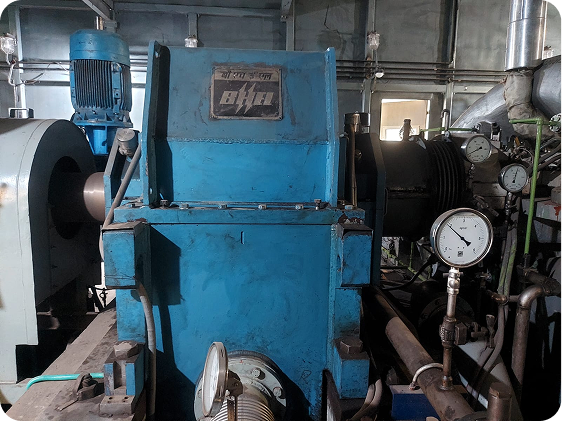
Figure 1 — Turbine-driven industrial blower under study
Vibration Monitoring Approach
Vibration measurements were performed using the ARGUS portable vibration monitoring system. The system enables rapid on‑site measurements and immediate vibration spectrum analysis, allowing maintenance personnel to identify mechanical faults directly during inspection.
Measurements were taken at the gearbox output drive end location using two frequency configurations to capture both high‑frequency gear behaviour and lower‑frequency mechanical faults.
Measurement Configuration
Two measurement ranges were used during inspection.
Frequency Setup 1 :
- 100 Hz – 10 kHz
- This range captures high‑frequency vibration signatures such as gear mesh frequencies and mechanical impacts.
Frequency Setup 2 :
- 100 Hz – 10 kHz
- This range captures high‑frequency vibration signatures such as gear mesh frequencies and mechanical impacts.
Measurement Results
Measurements indicated abnormal vibration levels at the gearbox output drive end.
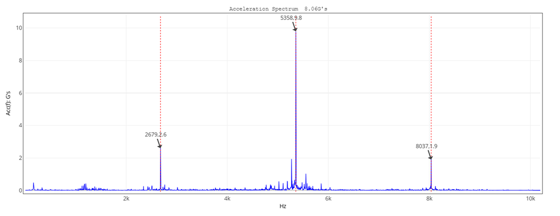
Maximum acceleration observed: 8.06 g
Figure 2 — Acceleration spectrum showing Gear Mesh Frequency (GMF) and harmonics
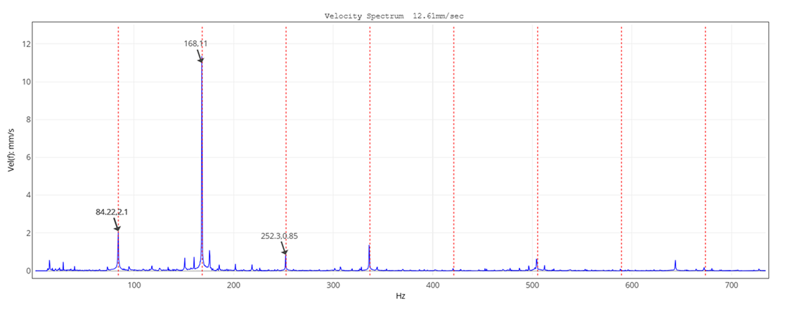
Maximum vibration velocity observed: 12.61 mm/s
Figure 3 — Velocity spectrum highlighting dominant 2× running frequency component
The measured vibration velocity exceeded limits typically defined in ISO 20816 vibration severity guidelines, indicating that the machine was operating in a critical vibration condition and required further diagnostic analysis.
Vibration Spectrum Analysis
FFT spectrum analysis revealed several diagnostic indicators.
A clear Gear Mesh Frequency (GMF) component was observed around 2679 Hz along with multiple harmonics. The presence of harmonics indicates abnormal interaction between gear teeth during meshing.
In addition, the velocity spectrum displayed a dominant vibration peak near twice the running frequency. A strong 2× running frequency component is a well‑known vibration signature associated with shaft or gear misalignment in rotating machinery.
Fault Diagnosis
Based on vibration analysis, the following indicators were observed:
- Elevated vibration velocity exceeding acceptable limits
- Gear mesh frequency and harmonics present in the spectrum
- Dominant 2× running frequency component
- Elevated vibration acceleration levels
These indicators collectively confirmed the presence of gear misalignment within the turbine‑blower gearbox drive train
Misalignment alters the contact pattern between gear teeth and increases dynamic forces during gear meshing, resulting in higher vibration amplitudes and accelerated mechanical wear.
Recommended Maintenance Action
Based on the diagnostic findings, the following maintenance actions were recommended:
- Inspection of gearbox alignment
- Verification of turbine‑gearbox coupling alignment
- Inspection of gear tooth contact patterns
- Verification of backlash and meshing conditions
- Post‑maintenance vibration verification to confirm condition improvement
Maintenance Impact and Risk Avoided
If left uncorrected, gearbox misalignment can lead to progressive gear damage, bearing wear, and eventual gearbox failure.
Typical maintenance activities required in such cases include gearbox alignment correction, bearing replacement, gear inspection, and lubrication system servicing.
Potential maintenance cost avoided:₹20 – ₹60 lakh
If severe gear damage occurs, repair costs can escalate significantly.
Potential production loss avoided (2 days): ₹30 – ₹50 lakh
Early detection using ARGUS vibration monitoring allowed maintenance teams to investigate the issue during a planned maintenance window, reducing the risk of unexpected equipment failure.
ARGUS Solution
ARGUS vibration monitoring systems support predictive maintenance and condition monitoring of critical rotating equipment across industries.
Typical monitored equipment includes gearboxes, turbines, compressors, pumps, motors, fans, blowers, and generators.
ARGUS solutions are available as portable diagnostic instruments as well as permanently installed online monitoring systems, enabling facilities to detect developing mechanical faults early and reduce unplanned downtime.